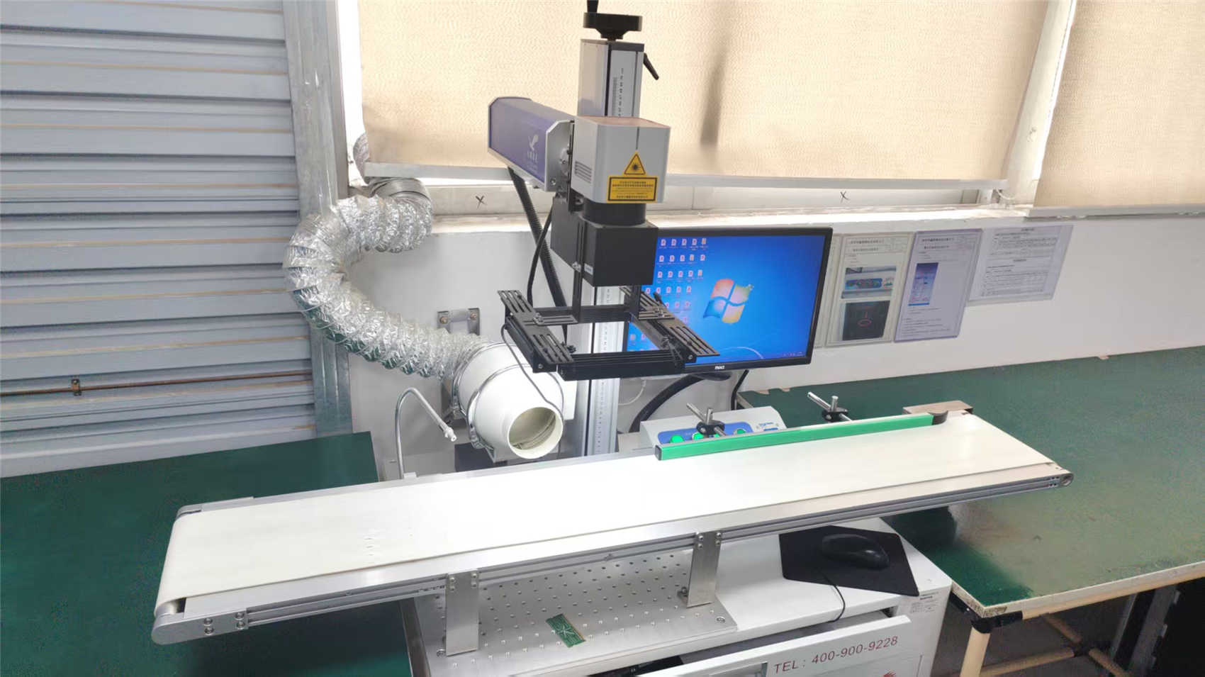
Selected professional materials and mechanical processing configurations engineered for Singapore aerospace and laboratory prototyping requirements.
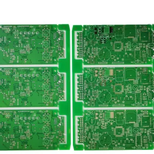
In the rapidly developing high-speed electronic space, standard FR-4 (Flame Retardant 4) glass epoxy laminates often fail to meet the performance criteria necessary for microwave and radio-frequency (RF) systems. Standard laminates display high signal attenuation, significant dielectric loss, and structural variations in their dielectric constant (Dk) across high operating frequencies. To maintain signal integrity in modern wireless protocols, engineers in Singapore's defense, aerospace, and telecommunications sectors increasingly demand Rogers high-frequency PCB substrates.
Rogers materials, consisting of ceramic-filled hydrocarbon and polytetrafluoroethylene (PTFE) composites, are engineered to deliver low electrical loss, low thermal expansion, and uniform dielectric constant stability. By implementing these substrates, designers can limit dispersion and phase jitter in high-frequency applications, which is essential for radar, cellular base stations, and high-performance wireless local area networks.
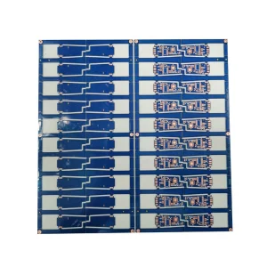
Singapore acts as an industrial hub for high-value advanced manufacturing, hosting research institutions and R&D facilities at sites like the Jurong Innovation District and Changi Business Park. The local ecosystem focuses on high-complexity, low-to-medium volume production, demanding high-frequency components for satcom (satellite communications), autonomous vehicles, marine navigation, and IoT networks.
Singapore's domestic market depends on rapid prototyping capabilities and material accessibility. High-performance projects require sourcing from specialized suppliers that can deliver certified raw Rogers laminates (such as RO4003C, RO4350B, and RT/duroid) alongside precise machining, plating, and multi-layer hybrid stacking services.
At millimeter-wave frequencies (30 GHz to 300 GHz), the attenuation of electrical signals increases significantly. Dielectric loss (represented by the dissipation factor or loss tangent, Df) is the primary driver of signal degradation in the substrate. While a typical FR-4 board exhibits a Df of approximately 0.015 to 0.020, a Rogers laminate like the RO4350B exhibits a Df of 0.0037, reducing thermal energy loss and improving signal strength at high frequencies.
Detailed electrical, thermal, and mechanical properties of common high-frequency microwave substrates compared to standard epoxy materials.
| Material Designation | Dielectric Constant (Dk @ 10GHz) | Dissipation Factor (Df @ 10GHz) | Thermal Conductivity (W/m/K) | CTE z-axis (ppm/°C) | Primary Industrial Use Case |
|---|---|---|---|---|---|
| Standard FR-4 | 4.2 - 4.7 | 0.015 - 0.020 | 0.25 | 175 | General Consumer Tech |
| Rogers RO4003C | 3.38 ± 0.05 | 0.0027 | 0.71 | 46 | Radar & Satcom Systems |
| Rogers RO4350B | 3.48 ± 0.05 | 0.0037 | 0.69 | 32 | 5G Transceivers & LNBs |
| Rogers RO3003 | 3.00 ± 0.04 | 0.0010 | 0.50 | 25 | 77 GHz Automotive Radar |
| RT/duroid 5880 | 2.20 ± 0.02 | 0.0009 | 0.20 | 237 | Military Avionics / Spaceflight |
Using Rogers materials for a complete multilayer PCB stackup can increase material costs significantly. To balance budgets, engineering designers often specify hybrid multilayer boards. These designs integrate Rogers high-frequency laminates on outer signal layers with standard, cost-efficient FR-4 cores and prepregs for internal structural or low-speed routing layers.
Fabricating hybrid boards requires careful coordination between the factory and the design team. Differences in coefficient of thermal expansion (CTE) and curing temperatures between FR-4 and PTFE or hydrocarbon laminates can lead to internal stresses, warpage, or delamination during assembly. Controlling thermal profiles during pressing, drilling, and chemical plating steps is necessary to ensure reliability.
High-frequency circuits operate on controlled impedance transmission lines, including microstrip, stripline, and coplanar waveguides. A minimal variation in trace width, copper thickness, or dielectric height can alter trace impedance, resulting in signal reflections, reduced return loss, and increased EMI.
CoreByte's partner manufacturing facilities utilize advanced lithography systems and precision micro-etching lines to maintain track width tolerances within ±5%. Standard testing protocols include using Time Domain Reflectometers (TDR) to verify impedance tolerances across every batch before shipping to customers in Singapore.
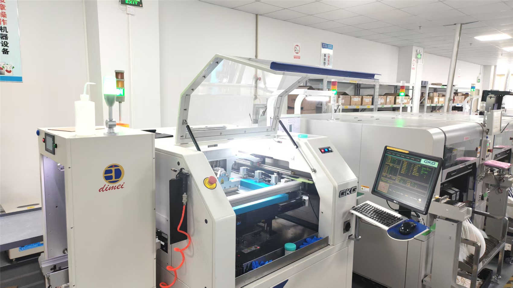
While Singapore serves as a hub for system-level design and regional program management, high-volume production and complex SMT assembly often leverage mainland China's supply chains. CoreByte Storage Technology Co., Ltd. works within this framework, providing memory and DRAM solutions alongside quick-turn PCB fabrication. Established in 2016, CoreByte operates a modern manufacturing facility with a building area of approximately 320㎡, generating an annual export revenue of around USD 12 million. The company's team of 85 R&D engineers and 45 quality control inspectors support high-speed, high-density system designs.
CoreByte implements quality management systems derived from ISO9001, combined with automated optical inspection (AOI) and high-temperature aging tests, to maintain product stability and compatibility. Operating with a network of over 1,200 supply chain partners, CoreByte supports developers in Singapore by bridging the gap between local prototyping and volume-optimized overseas production, managing lead times, material authenticity, and compliance processes.
Frequently asked engineering and sourcing questions from hardware designers and procurement specialists in Singapore.
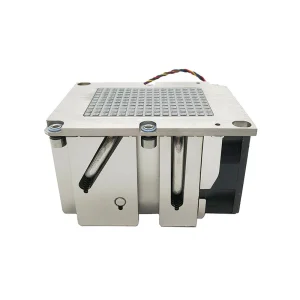
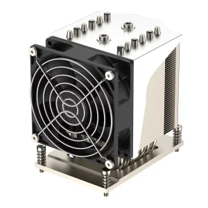
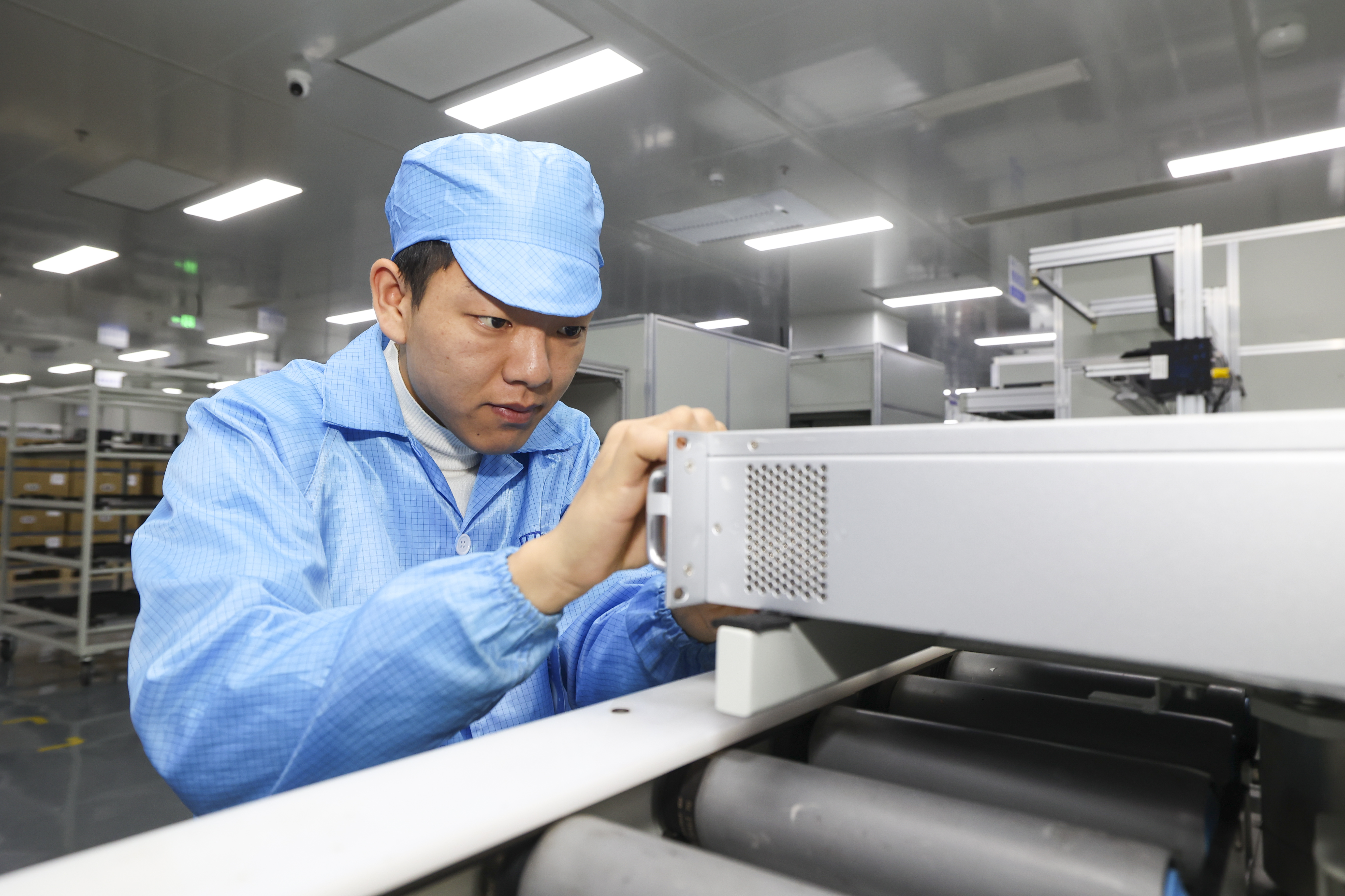
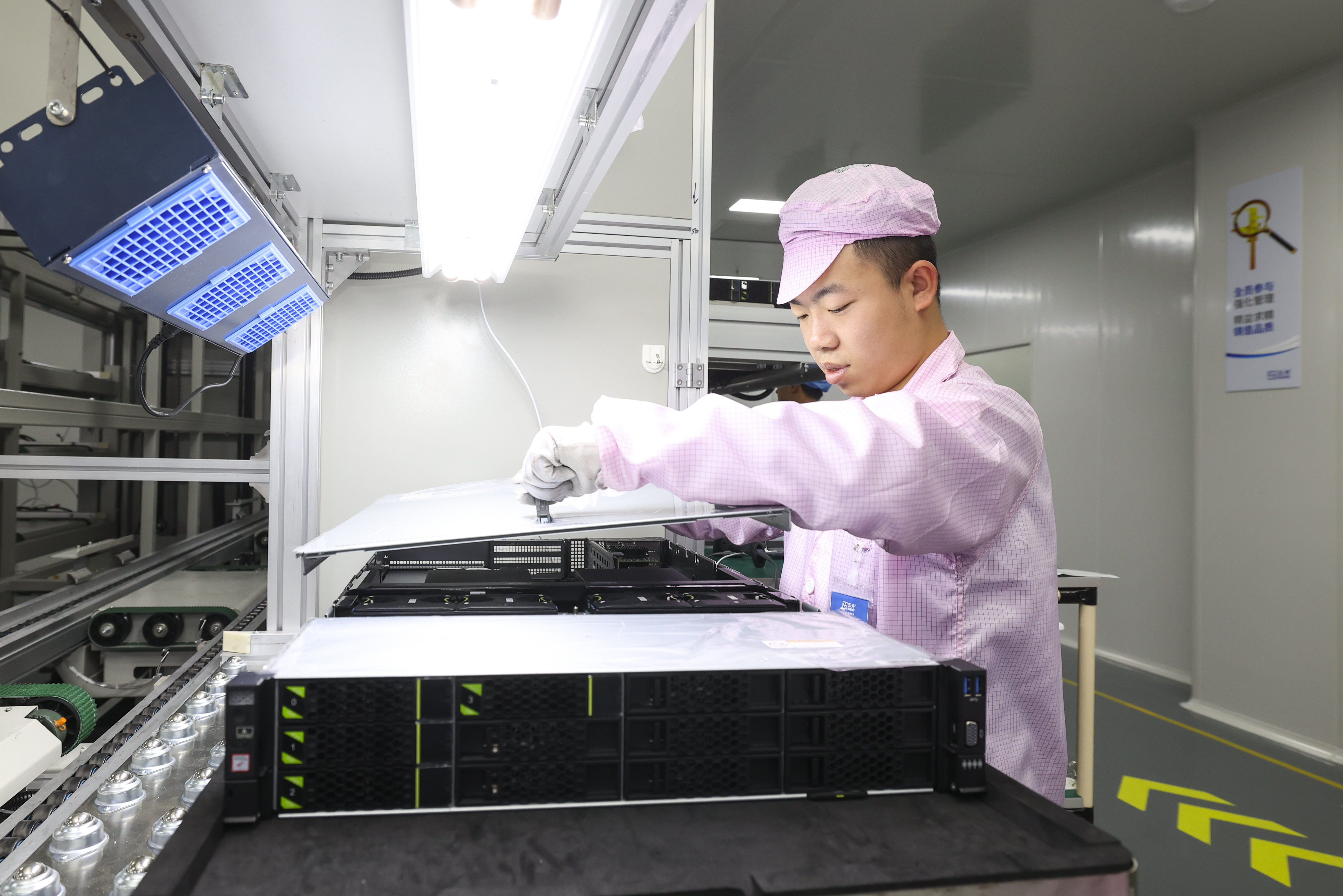
Complementary high-speed semiconductor assemblies and thermal control systems designed for Singapore edge networks, server racks, and data center deployment.
Send us your fabrication requirements, Gerber files, and laminate specification preferences (RO4003C, RO4350B, or custom stackups). Our engineers will review and provide a quote.
Send Inquiry Now